Epipolar geometry From Wikipedia, the free encyclopedia
Epipolar geometry is the geometry of stereo vision. When two cameras view a 3D scene from two distinct positions, there are a number of geometric relations between the 3D points and their projections onto the 2D images that lead to constraints between the image points. These relations are derived based on the assumption that the cameras can be approximated by the pinhole camera model.
스테레오 비전의 Geometry 이다. 두 카메라가 두개의 다른 위치에서 3차원 장면을 볼때, 3차원 포인트와 그것이 투영된 2차원 이미지 상에는 이미지 포인트 사이에서 제약을 야기하는 많은 기하학적 관계가 있다. 이러한 관계는 카메라가 핀홀 카메라 모델이라는 가정에 기초하여 유도된다.
즉 Epipolar geometry는 동일한 3차원 점에대한 영상을 서로 다른 두 지점에서 획득했을 때 두 이미지에서의 매칭쌍들 사이의 기하학적 관계를 다룬다.
Epipolar geometry
The figure below depicts two pinhole cameras looking at point X. In real cameras, the image plane is actually behind the focal center, and produces an image that is the symmetry about the focal center of the lens. Here, however, the problem is simplified by placing a virtual image plane in front of the focal center i.e optical center of each camera lens to produce an image not transformed by the symmetry. OL and OR represent the centers of symmetry of the two cameras lenses. X represents the point of interest in both cameras. Points xL and xR are the projections of point X onto the image planes.
아래 그림은 점 X를 바라보는 두개의 핀홀 카메라를 보여준다. 실제 카메라에서 이미지면(하늘색 사각형)은 초점 중심 뒤에 있으며 렌즈의 초점 중심에 대한 대칭 이미지를 생성한다. 하지만 그 문제는 아래 그림과 같이 이미지면을 초점 중심 앞에 배치함으로써 단순화 할 수 있다. OL과 OR은 두 카메라 렌즈 각각의 대칭 중심을 나타내며 X는 두 카메라의 관심지점을 나타낸다. 점 XL 과 XR은 점 X의 각 이미지평면으로의 투영을 나타낸다.
Each camera captures a 2D image of the 3D world. This conversion from 3D to 2D is referred to as a perspective projection and is described by the pinhole camera model. It is common to model this projection operation by rays that emanate from the camera, passing through its focal center. Note that each emanating ray corresponds to a single point in the image.
각 카메라는 3차원 세계의 2차원 이미지를 캡쳐한다. 이 3차원에서 2차원으로의 변환은 원근 투영(perspective projection)이라고 하며 핀홀 카메라 모델에서 설명이 된다. 이런 투영 모델은 보통 초점 중심을 통과하는 ray로 아래와 같이 표현을 한다. 각 ray는 하나의 점에 대응한다.
Epipole or epipolar point
Since the optical centers of the cameras lenses are distinct, each center projects onto a distinct point into the other camera's image plane. These two image points are denoted by eL and eR and are called epipoles or epipolar points. Both epipoles eL and eR in their respective image planes and both optical centers OL and OR lie on a single 3D line.
카메라 렌즈의 광학 중심이 다르기 때문에 각 중심은 각 이미지 평면의 다른 점으로 투영된다. 두 이미지 포인트는 eL, eR로 표시되며 epipoles 또는 epipolar points라고 부른다.
각 이미지 평면에서의 epipole(eL, eR)과 초점 중심(oL, oR)은 모두 3차원 상에서 같은 선 위에 놓여있다.
Epipolar line
The line OL–X is seen by the left camera as a point because it is directly in line with that camera's lens optical center. However, the right camera sees this line as a line in its image plane. That line (eR–xR) in the right camera is called an epipolar line. Symmetrically, the line OR–X seen by the right camera as a point is seen as epipolar line eL–xLby the left camera.
선 oL - X은 왼쪽 카메라의 optical canter와 연결이 되어있기 때문에 점으로 보인다. 하지만 오른쪽 카메라는 이미지 평면에서 선으로 보인다.
여기서 오른쪽 카메라의 eR - Xr을 epipolar line이라고 부른다. 대칭적으로 오른쪽 카메라에서 점으로 보이는 oR - X는 왼쪽 카메라에 의해 epipolar line eL - XL으로 보여진다.
An epipolar line is a function of the position of point X in the 3D space, i.e. as X varies a set of epipolar lines is generated in both images.
Since the 3D line OL–X passes through the optical center of the lens OL, the corresponding epipolar line in the right image must pass through the epipole eR (and correspondingly for epipolar lines in the left image). All epipolar lines in one image contains the epipolar point of that image. In fact, any line which contains the epipolar point is an epipolar line since it can be derived from some 3D point X.
Epipolar line은 점 X의 위치와 상관관계에 있으며 X가 변하면 epipolar line set이 다시 계산이 되어야 한다.
3차원 선 oL - X 는 oL의 optical center를 통과하기 때문에 오른쪽 이미지 평면에서의 대응되는 epipolar line 은 epipole eR을 통과하여야 한다.
모든 epipolar line은 해당 이미지 평면의 epipolar point를 포함한다.
Epipolar plane
As an alternative visualization, consider the points X, OL & OR that form a plane called the epipolar plane. The epipolar plane intersects each camera's image plane where it forms lines—the epipolar lines. All epipolar planes and epipolar lines intersect the epipole regardless of where X is located.
점 X, oL과 oR를 가지는 평면을 epipolar plane이라 한다. epipolar plane은 각 카메라의 이미지 평면과 epipolar line에서 교차한다.
Epipolar constraint and triangulation
두 카메라간의 위치관계를 알고있다면 두가지 중요한 사실을 알 수 있다.
- If the projection point xL is known, then the epipolar line eR–xR is known and the point X projects into the right image, on a point xR which must lie on this particular epipolar line. This means that for each point observed in one image the same point must be observed in the other image on a known epipolar line. This provides an epipolar constraint: the projection of X on the right camera plane xR must be contained in the eR–xR epipolar line. Note also that all points X e.g X1, X2, X3 on the OL–XL line will verify that constraint. It means that it is possible to test if two points correspond to the same 3D point. Epipolar constraints can also be described by the essential matrix or the fundamental matrix between the two cameras.
- If the points xL and xR are known, their projection lines are also known. If the two image points correspond to the same 3D point X the projection lines must intersect precisely at X. This means that X can be calculated from the coordinates of the two image points, a process called triangulation.
투영점 xL을 알고있으므로 epipolar line eR - xR 을 알 수 있으며 점 X는 오른쪽 이미지 평면으로 투영이 되고 이 특정 epipolar line위에 놓여야 한다. 이 부분이 첫번째 epipolar constraint 이다.
다시 정리하면 오른쪽 카메라 이미지 평면의 xR로 투영되는 X는 eR - xR epipolar line 에 포함되어야 한다.
epipolar constraint는 두 카메라간의 essential matrix, fundamental matrix 로도 기술 할 수있다.
만약 점 xL 과 xR을 알고 있다면 투영된 선도 알 수 있다. 두 이미지에서의 점이 동일한 3차원 점이라면 투영된 선은 정확하게 X에서 교차한다. 이것은 두 이미지상의 점과 triangulation 을 이용하여 X를 계산 할 수 있다는 것을 의미한다.
정리하면..
왼쪽 이미지 평면의 점으로부터 오른쪽 이미지 평면에 대응되는 점을 유일하게 결정할 수는 없지만 그 점이 지나는 직선인 epipolar line은 유일하게 결정할 수 있다.
또 양쪽의 이미지 평면에서 대응되는 점을 알고있다면 삼각법을 통해서 3차원 좌표를 정확하게 계산 할 수 있다.
Simplified cases
The epipolar geometry is simplified if the two camera image planes coincide. In this case, the epipolar lines also coincide (EL–PL = ER–PR). Furthermore, the epipolar lines are parallel to the line OL–OR between the centers of projection, and can in practice be aligned with the horizontal axes of the two images. This means that for each point in one image, its corresponding point in the other image can be found by looking only along a horizontal line. If the cameras cannot be positioned in this way, the image coordinates from the cameras may be transformed to emulate having a common image plane. This process is called image rectification.
두 카메라 이미지 평면이 일치하면 epipolar geometry또한 단순화 할 수 있다.(두 카메라가 나란히 있는 경우 같음)
이 경우 epipolar line이 일치하게 되고 epipolar line은 중심점 oL - oR 선과도 평행하게 된다. 즉, 한 이미지의 각 점에 대하여 다른 이미지의 일치하는 점을 가로선만 보면서 찾을 수 있다.
카메라가 이렇게 배치될 수 없다면 이미지 평면을 변형 시켜서 위와 같은 방법으로 계산을 할 수 있는데 이 프로세스를 rectification 이라 한다.


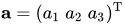 and
and  . Then, defining matrix:
![[\mathbf {a} ]_{\times }={\begin{bmatrix}\,\,0&\!-a_{3}&\,\,\,a_{2}\\\,\,\,a_{3}&0&\!-a_{1}\\\!-a_{2}&\,\,a_{1}&\,\,0\end{bmatrix}}](https://wikimedia.org/api/rest_v1/media/math/render/svg/380c2a9db62bb8d5a7275529427e55952cc19b9e)
![{\displaystyle \mathbf {a} \times \mathbf {b} =[\mathbf {a} ]_{\times }\mathbf {b} .}](https://wikimedia.org/api/rest_v1/media/math/render/svg/6ab16fc943f87547006ec9ddd66d083bd169aeb9)


